Introduction
The Nokia 3310 LCD is well known in the electronics community; I decided to have some fun and get it to do things the designers probably weren’t intending!
This LCD is a monochrome graphics LCD with a resolution of 84×48 and while relatively old (1998), it’s great for its very low price (eBay, etc.)
I wrote up some Processing and Arduino sketches to encode/decode video and play it on this Nokia LCD.
Nokia 3310 LCD
The Nokia 3310 LCD uses the PCD8544 controller IC — it has an easy to use SPI protocol, and handles all the hard work of driving this display (multiplexing, generating bias voltages, ect.) Using the display is relatively easy with any microcontroller. I used a breakout board for ease of access on a breadboard/stripboard.
Construction
Adafruit has written a nice Arduino library and tutorial for using this display. It was perfect for my needs, as their library can easily draw text, lines, rectangles, circles and other shapes to the display.
I soldered up a simple shield for driving the display, and a few capacitive buttons. I used capacitive buttons as I didn’t have any normal buttons on me. The piece of code I used for these buttons was found here on the Arduino site, and is connected directly to the buttons. No pull-up resistors were used in this case. The buttons were connected to the following pins:
- Select File — Pin 19 (analog A5)
- Toggle FPS — Pin 18 (analog A4)
- Play — Pin 17 (analog A3)
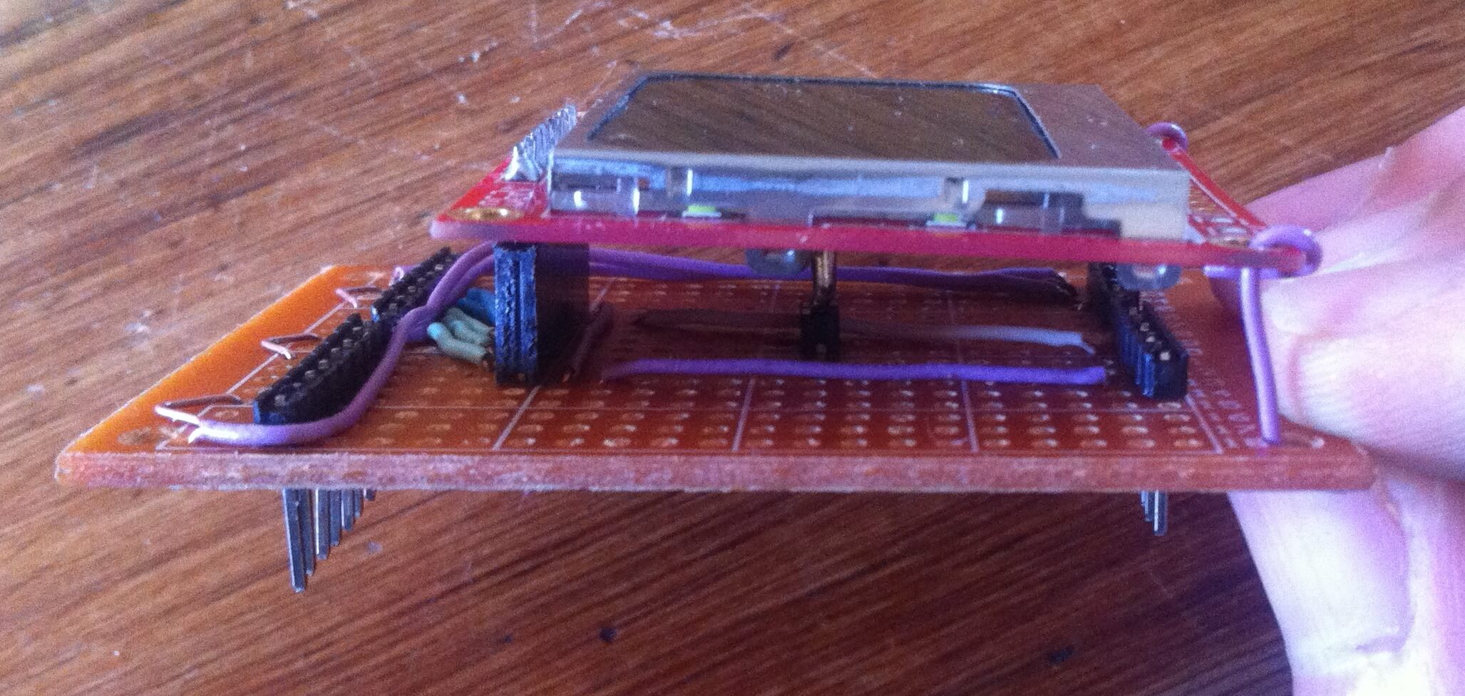
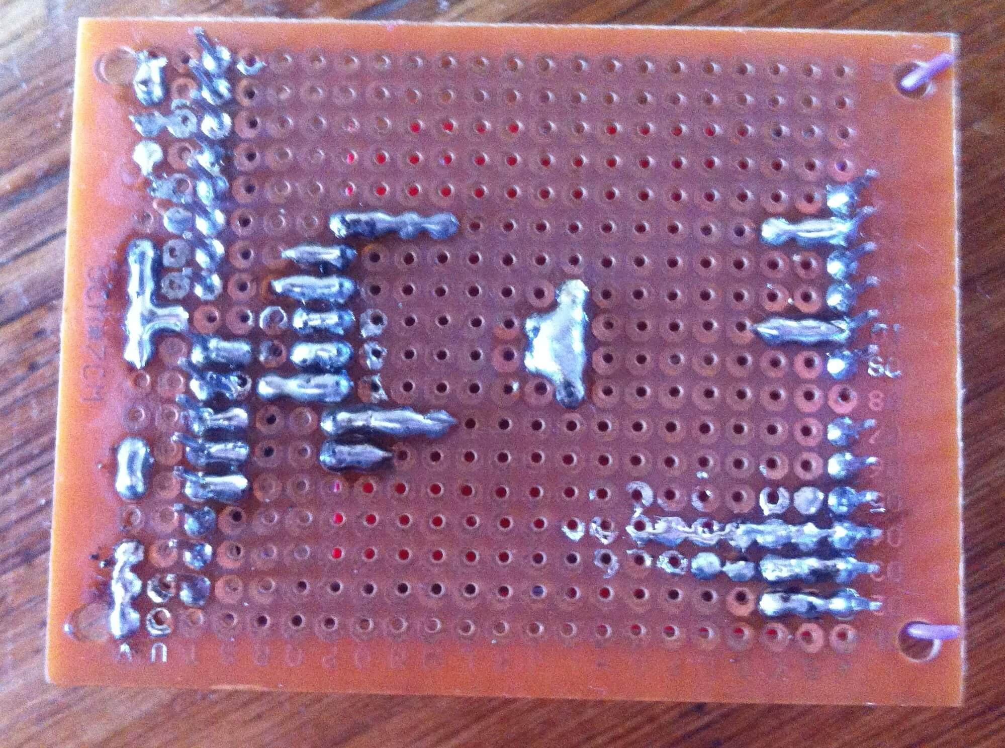
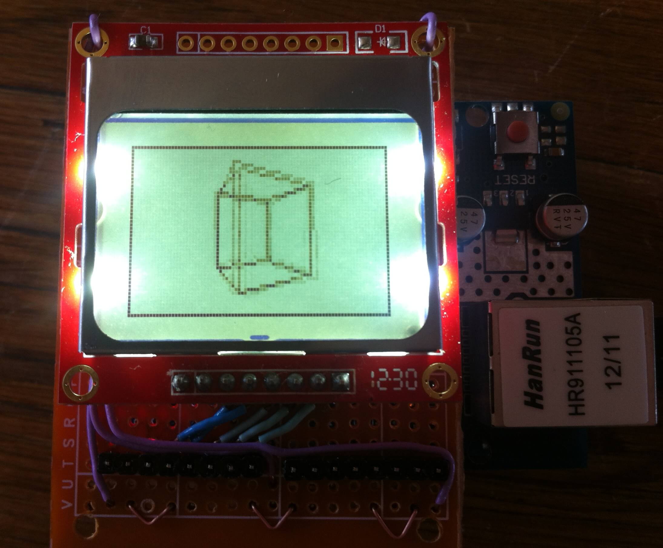
Here are some images of the shield I made (I apologise for the messy soldering, I needed this done in a hurry):
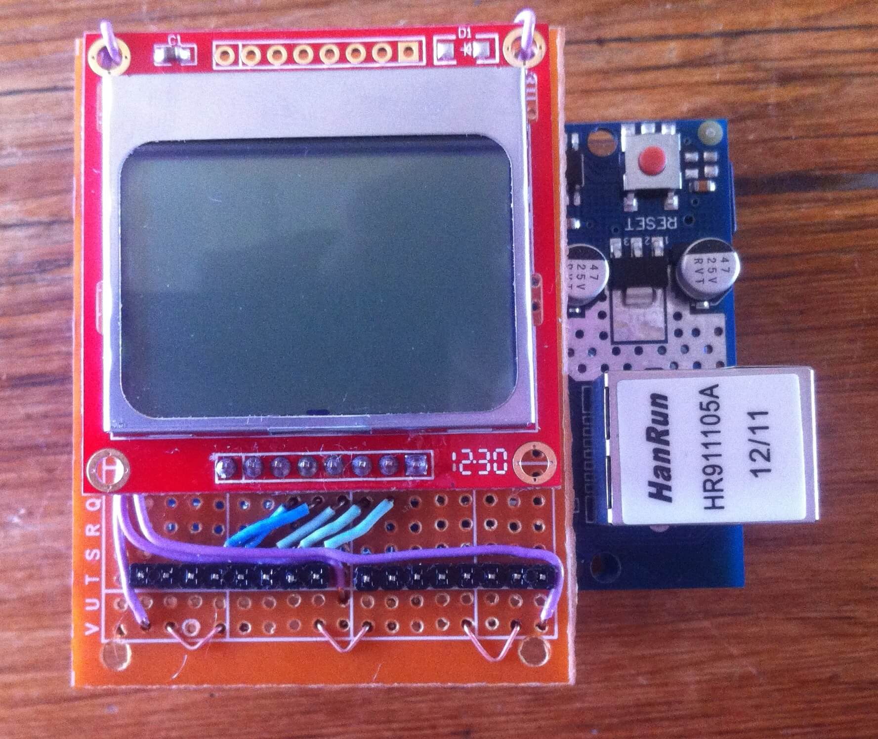
Playing video
I came across this video of a similar monochrome display playing video, using an ATMega88 and SD card. The video looked like it was using 1-bit dithering to be visible on a monochrome display, and was very recognisable. It’s worth a shot trying this with the Nokia LCD and Arduino, right? I had also purchased an Ethernet shield which happens to have a SD card slot, which was convenient.
First of all, I came up with a format for saving my data. The encoded data file would consist of ASCII characters. If the ASCII character was from 0x00 to 0x3F in hex (the first 6 bits, or from B000000 to B111111) then it would be treated as data.
If I wanted the first 6 pixels of the first row on the frame buffer to appear in this binary pattern: 101010 then I would set the character to be 0x2A (B101010), and increases the X coordinate by 6. If I repeat this character, it would set the next 6 pixels to 101010, and so on. This is what is used to set the image of the display.
When this is done 14 times, I end up with 84 pixels which is exactly the width of one of the rows of the display. Perfect fit!
Now, if the ASCII character is over 0x3F it is a control character. This is a command that can trigger a certain function in the program.
Here are the control characters:
0x7B— New line — Increments the Y-axis by one, use this when you have written all 14 data characters for the row to go on to the next one and carry on sending your data.0x7C— Reset the X and Y coordinates — Use this when you have filled up the whole display, and need to start at the beginning point for a new image.0x7D— Update display — This sends the data in the frame buffer to the display and displays it.
I wrote a Processing script to render a simple 3D Cube and save each frame to a file in the sketch’s project folder using the protocol above (code at the bottom of the page).
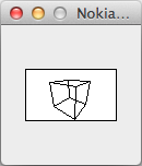
The script saved the data to a file called data.dat. Next, I formatted my MicroSD card with the FAT32 format, and copied the data.dat file onto it.
Writing the Arduino video player program was the most difficult part. I used the SD library included with Arduino to read the files of the SD card and wrote up a file chooser what uses the buttons on the shield, and a routine to read data from the chosen file off the SD card, draw the images and handle the commands. Everything worked out OK in the end after a day of work, and I had a working product. However, I still needed to finish my goal of displaying video.
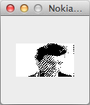
Next, I conducted some research on Dithering. I then discovered Windell Oskay’s writeup on Atkinson dithering and some Processing sample code. The example converted real-time video from a webcam to 1-bit dithered images — just what we need. I then modified the program with a output resolution of 84×48, and gave it a video as the input file. (If you want to use a different file, make sure it is 84×48 with fairly high contrast for best results with the dithering, though any resolution should still work fine. For the video, I decided to play the music video of Rick Astley’s “Never Gonna Give You Up” because, well…
Source code
Conclusion
The results were impressive. I’m satisfied with the 15FPS I got using C++ and the Arduino/Adafruit libraries. Improvements are definitely possible with using more raw methods of access to the SD card and display.
It should be noted that the other version I had seen linked above had a higher resolution display and was running at half the clock speed (8Mhz compared to Arduino’s 16Mhz). This goes to show how optimisation can lead to better results.
Comments