
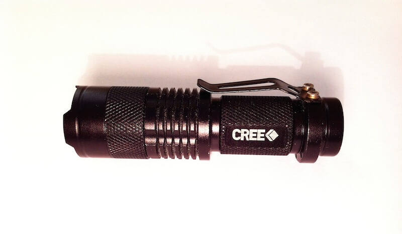
Around a month ago I purchased a Sipik SK68 LED flashlight clone on eBay, for a grand total of $4.04! Shipping took around three weeks which isn’t bad considering it was free, but when I started using it there was a rather annoying design flaw..
The Flashlight
It is focusable and runs on one AA 1.5V battery, or one 14500 3.7V lithium battery. The brightness with a 14500 battery is around 300 lumens which is seriously bright. It’s a great deal for the price!
The Issue
This flashlight has one very poorly engineered feature: its modes. It has three modes, Bright, Dim and Strobe, but to switch modes the light has to be turned off and back on again. This is a huge inconvenience when you switch it off in the Bright mode, as on the next power cycle it will be in Dim mode. You have to cycle modes to get it back to normal again. This frustrated me, and I had no need for the other modes anyway, only full brightness. Time for a fix!
Disassembly
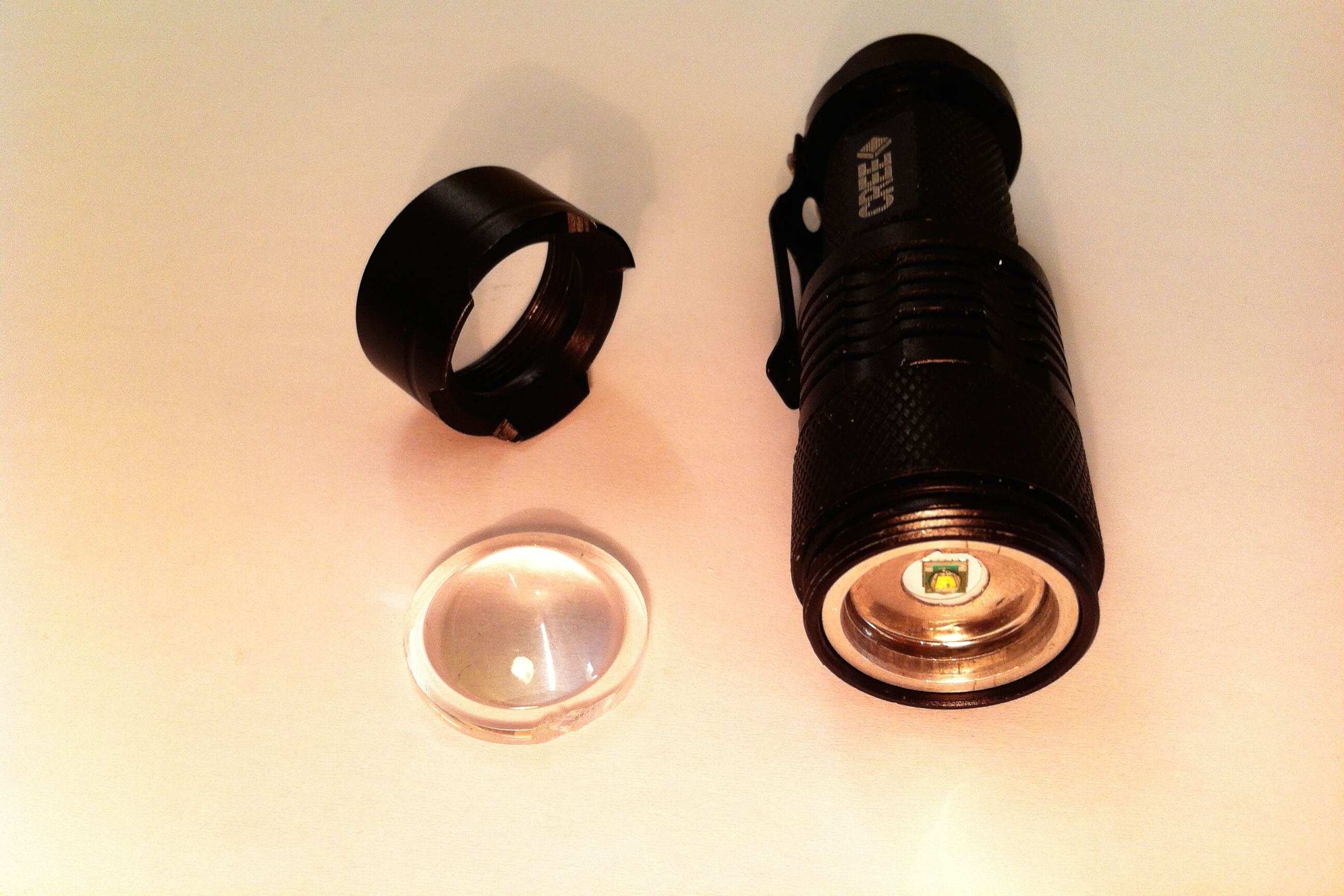
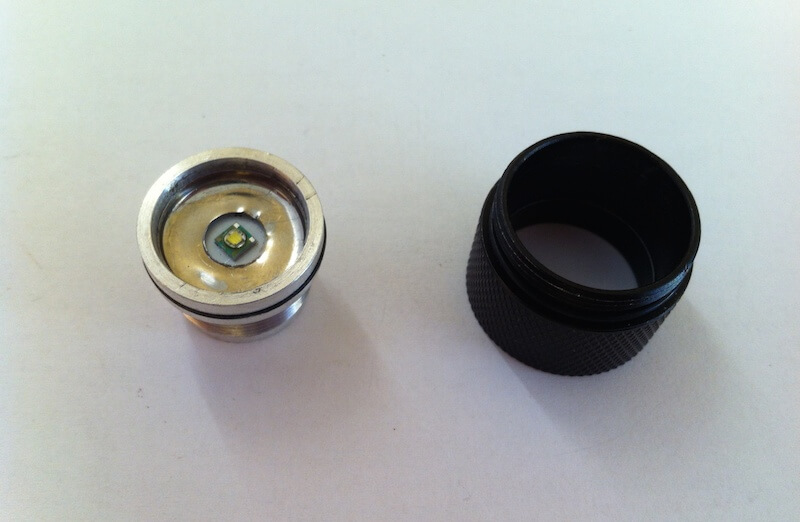
I started by unscrewing the lens cap, revealing the Cree LED emitter and lens.
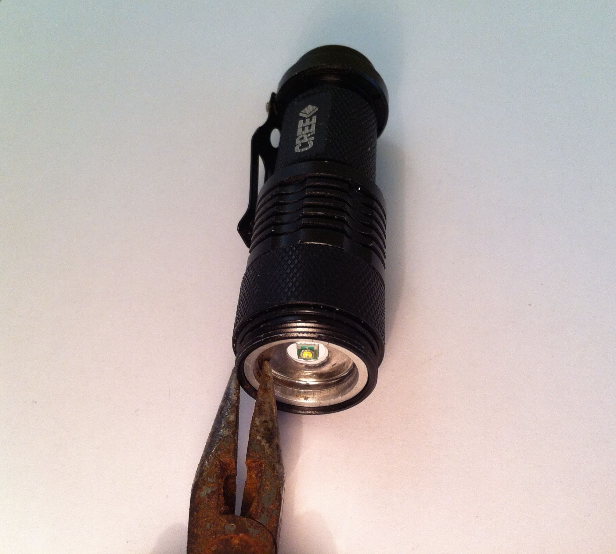
Next, the LED “pill” needs to be removed — this holds the driver and LED emitter. The focusing ring can rotate freely, but the LED pill (the silver aluminium part) is tight. Unscrew it by holding it to the focusing ring with pliers, and unscrew them both. The pill will unscrew, then just pull the pill out.
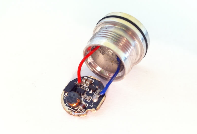
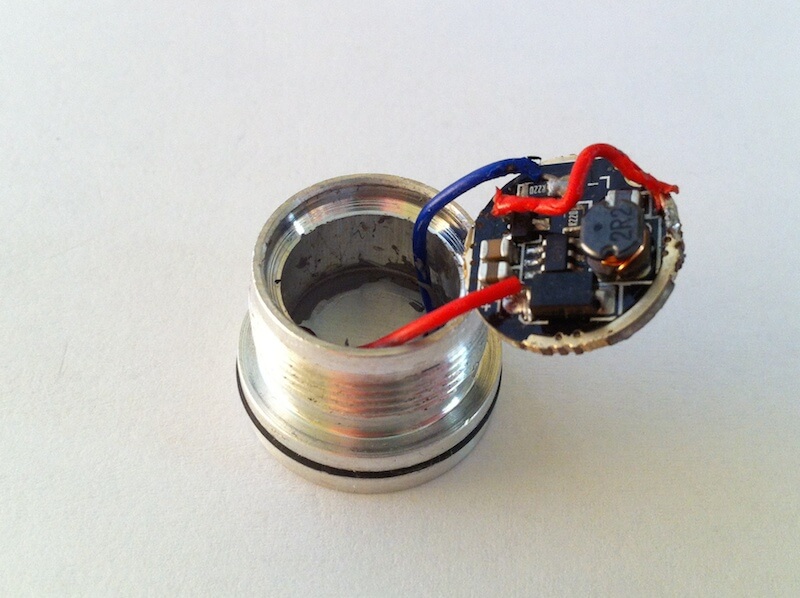
At the bottom of the pill there was a circuit board with markings JX2205. I couldn’t find any valuable info about it online. Simply pop the circuit board out with a screwdriver.
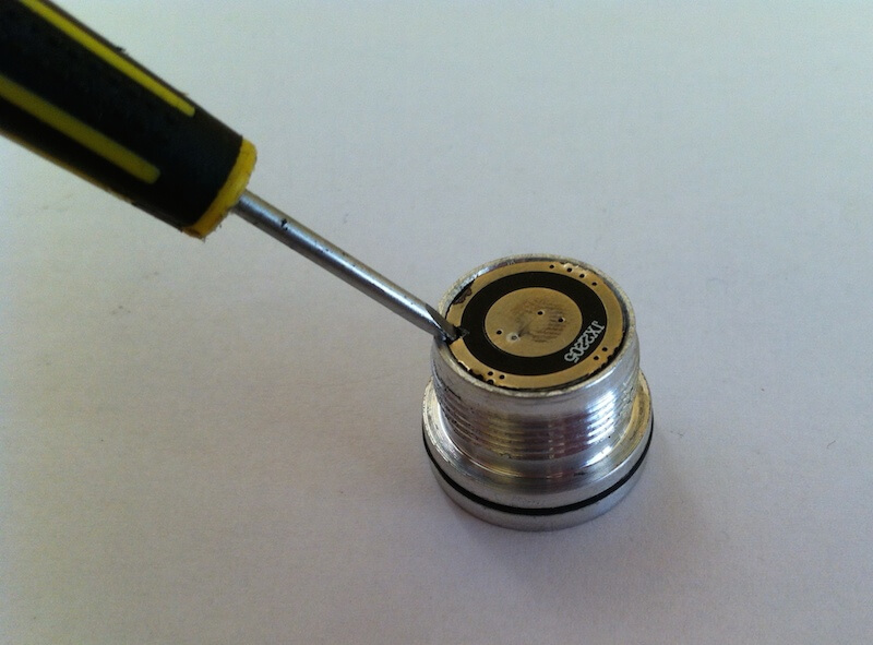
The circuit board contains a boost converter — this boosts the voltage from, say, a 1.5V battery to the higher voltage needed by the LED. It also provides a constant current, which is required for all high-power LEDs.
The Fix
After visually inspecting the board, I spotted two ICs (chips) which could have been the culprits.
One was a six legged IC labelled 601, which turned out to be the boost converter driver chip. Nothing to see here.
The other one which I assumed was a transistor turned out to be our culprit. It had only 3 legs and was labelled 8133A. After some Googling I found a schematic for it labelled “5W three function LED driver IC”:
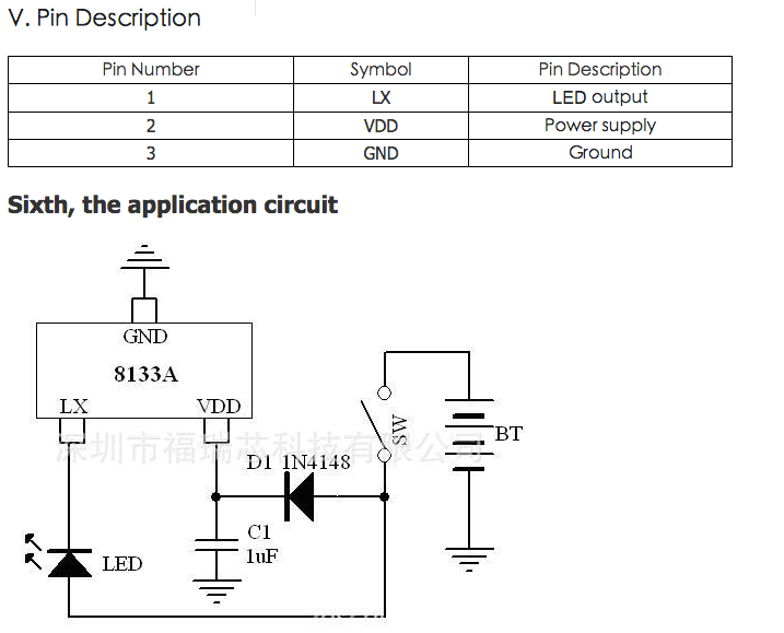
The schematic shows that it includes a transistor between pin 1 (LX) and 3 (Ground) which switches the LED on and off. All we need to do to bypass it is to connect pins 1 and 3 together.
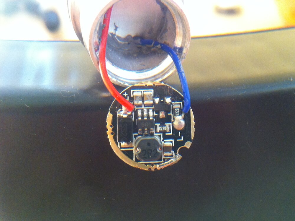
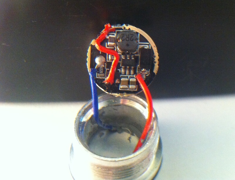
After checking the board, the whole outer ring acts as a Ground conductor, so we can simply solder on a jumper between pin 1 on the chip to the outer ground, as shown below by the arrow:
After a quick, messy soldering job, the jumper was in place:
Now all that needs to be done is to reassemble the housing, and you’ll hopefully be holding a sweet 1-mode flashlight! The driver in many Sipik SK68 flashlights and clones may vary from different batches / manufacturers, however if your driver uses this chip then the process should be the same. If not, just search the part numbers of the ICs until you find the culprit.
Conclusion
This project was a great success and makes this flashlight an even better buy in my opinion. Please let me know if you try this!
Disclaimer: If you attempt this, it’s at your own risk. If you break your flashlight I will not be held responsible. This will obviously void any warranty, so be careful and good luck!
Comments